ESP32 boards to control them from external inputs. This will allow us to "decouple" the basic functionality we want the board to have from the actual code.Platformio on VSCode to create the universal driver.Why you need a Universal Pin Driver?
When programming embedded boards such as the ESP32, the code must be compiled to binary and flashed on the ROM of the board.
This means that whenever we want to modify the functionality, the code must be modified, recompiled and flashed again.
Technically speaking it is possible to create a system that allows the board to automatically update firmware when a new version is available.
Such a system is of course complicated to create and also, it would not work in situations in which there is no internet connection.
In this tutorial, we will create a Slave Universal Pin Driver that you can flash to all boards and will effectively decouple the firmware from the functionality that you need from the board.
The logic of the UPD (Universal Pin Driver)
The logic is this:
We will create and flash a firmware that will accept high level commands as strings (from Serial) and will execute them, reporting back the result.
Technically speaking, we will use commands in the following format: operation:mode:pin:value? where:
operationidentifies the type task we want to perform:modeis the mode we want to use to perform the operation:pinidentifies the pin we want to usevalue?in case of write operation, the value we want to write to the pin: .In case ofdigitalwrite, we will consider HIGH whenever the value is greater than 0
Some examples are:
write:digital:14:1: sets the pin 14 to HIGHwrite:analog:14:127: sets the pin 14 to 127 (analog half duty cycle)write:analog:13: reads the analog value of the pin 13
Coding the UPD
Installing the dependencies
We will use Platformio to create and code our UPD so be sure to install the Platformio extension for VSCode:
- Open VSCode
- Go to extensions and type
Platformio - Install the extension.
After the extension is installed, you will see the Platformio icon on the left toolbar.
Click the icon and select Create New Project.
Espressif ESP32 Dev Module and set the framework to Arduino.Now we are ready to start coding.
Handling the pin permissions
On the ESP32 board, each pin has different functionalities and different entitlements, meaning that some pins can do some operations while others cannot. Since our commands are "universal" we need to handle these different cases.
The following image shows the Pinout for ESP32 Dev Modules:
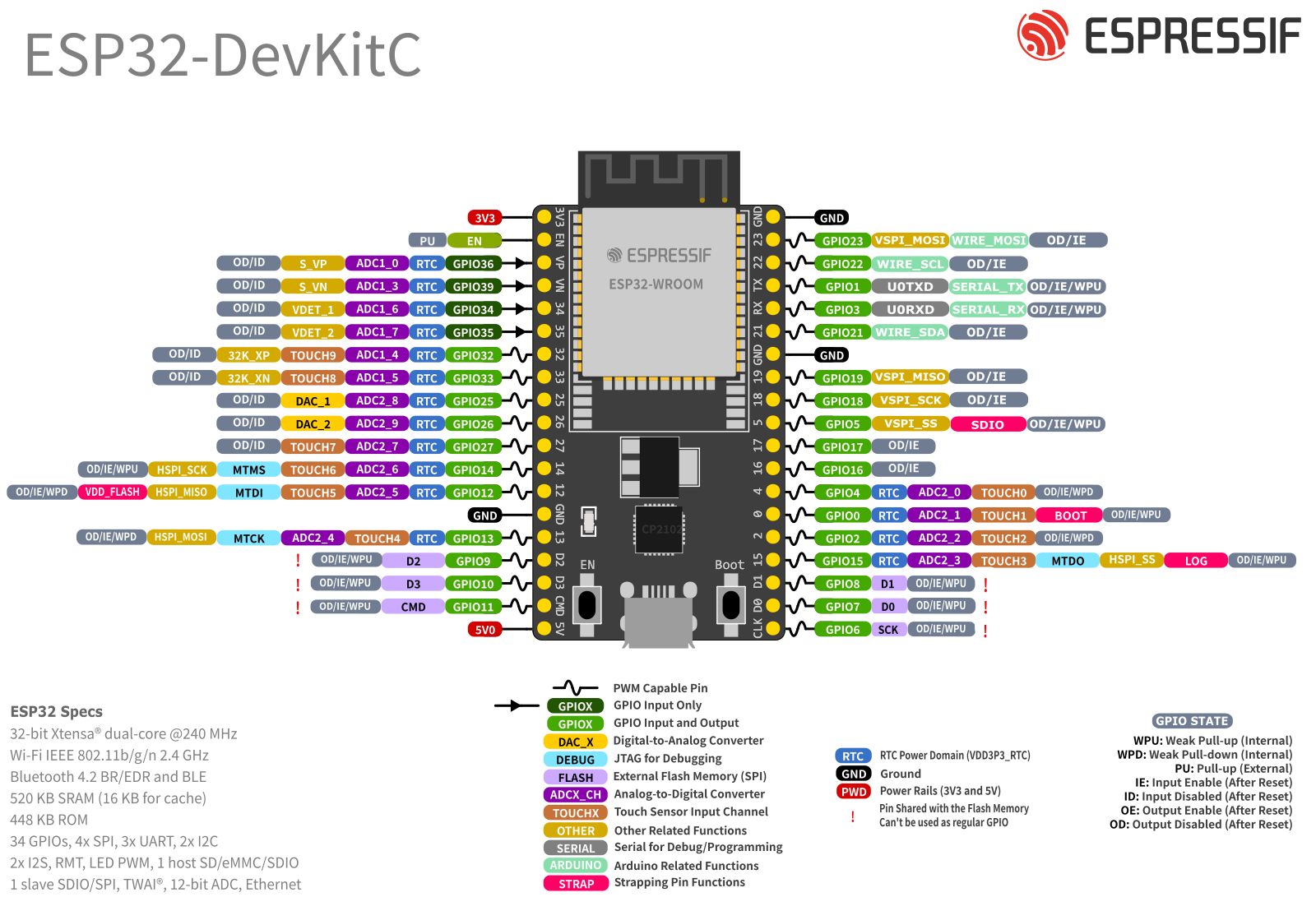
There are different versions of Dev Modules, be sure to always reference the sheet from your vendors for the correct pinout. Check out the official Espressif Documentation.
We are going to develop a very simple pin mapping that will allow us to very easily detect whether an incoming command can be executed or not.
To make everything more clear, let's create a file that contains some constants:
#define OP_READ "read"
#define OP_WRITE "write"
#define OP_MODE_DIGITAL "digital"
#define OP_MODE_ANALOG "analog"
Now we can create a file at the following path include/esp32_gpio_mapping.h with the following content:
#include <Arduino.h>
#include <map>
#include <vector>
#include "../include/defines.h"
enum class PinEntitlement { adc, dac, touch, i2c, spi, uart, pwm, rtc};
const std::vector<int> safePins = {4, 13, 14, 16, 17, 18, 19, 21, 22, 23, 25, 26, 27, 32, 33, 34, 35, 36, 39};

std::map<PinEntitlement, const std::vector<int>> pinMappings = {
    {PinEntitlement::adc, {4, 13, 14, 25, 26, 27, 32, 33, 34, 35, 36, 39}},
    {PinEntitlement::dac, {25, 26}},
    {PinEntitlement::touch, {4, 13, 14, 25, 26, 27, 32, 33}},
    {PinEntitlement::i2c, {21, 22}},
    {PinEntitlement::spi, {13, 14, 18, 19, 23}},
    {PinEntitlement::uart, {16, 17}},
    {PinEntitlement::pwm, {4, 13, 14, 16, 17, 18, 19, 21, 22, 23, 25, 26, 27, 32, 33}},
    {PinEntitlement::rtc, {4, 13, 14, 25, 26, 27, 32, 33, 34, 35, 36, 39}},
};

bool esp32GpioSafe(int pin, String operation)
{
    auto it = std::find(safePins.begin(), safePins.end(), pin);
    if (it == safePins.end())
        return false;
    if (operation == OP_WRITE)
    {
        return pin < 34;
    }
    return true;
}

bool esp32GpioEntitled(PinEntitlement function, int pin)
{
    auto vec = pinMappings[function];
    return std::find(vec.begin(), vec.end(), pin) != vec.end();
}
This file will contain the code that we will use to check for pin entitlements. The esp32GpioEntitled function allow us to see if a certain pin has the specified entitlement, while the esp32GpioSafe method will detect whether the pin is indeed an available one.
.h files and source files .cpp to optimize compile and linking time. However in very small projects such as this one, it is fine to condense declarations and implementations in single files to keep the number of files low.Parsing the commands
Now we will create the file that we will parse and execute the commands.
Create a new file at the following path: include/command.h with the following content. The code seems pretty long but really all we are doing is creating two functions:
bool parseCommand(String input, Command &cmd): this will try to parse and populate aCommandstruct (considering also the pin entitlements) and return whether the command is valid or not.String executeCommand(Command &cmd): execute a command and if present, returns the execution results.
#include <Arduino.h>
#include "../include/esp32_gpio_mapping.h"
#include "../include/defines.h"

struct Command
{
    String operation;
    String mode;
    int pin;
    int value;
};

int clamp(int value, int min, int max)
{
    if (value < min)
    {
        return min;
    }
    else if (value > max)
    {
        return max;
    }
    else
    {
        return value;
    }
}

String executeCommand(Command &cmd)
{
    if (cmd.operation == OP_READ)
    {
        pinMode(cmd.pin, INPUT);
        int value;
        if (cmd.mode == OP_MODE_DIGITAL)
        {
            value = digitalRead(cmd.pin);
        }
        else if (cmd.mode == OP_MODE_ANALOG)
        {
            value = analogRead(cmd.pin);
        }
        return ("read:" + String(cmd.pin) + ":" + String(value));
    }
    else if (cmd.operation == OP_WRITE)
    {
        pinMode(cmd.pin, OUTPUT);
        if (cmd.mode == OP_MODE_DIGITAL)
        {
            cmd.value = cmd.value > 0 ? HIGH : LOW;
            digitalWrite(cmd.pin, cmd.value > 0 ? HIGH : LOW);
        }
        else if (cmd.mode == OP_MODE_ANALOG)
        {
            analogWrite(cmd.pin, cmd.value);
        }
        return ("write:" + String(cmd.pin) + ":" + String(cmd.value));
    }
    return "error:unrecognized command";
}

bool parseCommand(String input, Command &cmd)
{
    int firstColon = input.indexOf(':');
    int secondColon = input.indexOf(':', firstColon + 1);

    if (firstColon == -1 || secondColon == -1)
    {
        return false;
    }

    cmd.operation = input.substring(0, firstColon);
    cmd.mode = input.substring(firstColon + 1, secondColon);

    if ((cmd.operation != OP_READ && cmd.operation != OP_WRITE) || (cmd.mode != OP_MODE_DIGITAL && cmd.mode != OP_MODE_ANALOG))
    {
        return false;
    }

    String pinStr = input.substring(secondColon + 1);
    cmd.pin = pinStr.toInt();
    if (!esp32GpioSafe(cmd.pin, cmd.operation))
    {
        return false;
    }
    if (cmd.operation == OP_WRITE)
    {
        int valueIndex = pinStr.indexOf(':');
        if (valueIndex == -1)
        {
            return false;
        }
        cmd.pin = pinStr.substring(0, valueIndex).toInt();
        cmd.value = clamp(pinStr.substring(valueIndex + 1).toInt(), 0, 255);
    }

    if (cmd.operation == OP_WRITE && cmd.mode == OP_MODE_ANALOG && !esp32GpioEntitled(PinEntitlement::dac, cmd.pin))
    {
        return false;
    }

    if (cmd.operation == OP_READ && cmd.mode == OP_MODE_ANALOG && !esp32GpioEntitled(PinEntitlement::adc, cmd.pin))
    {
        return false;
    }

    return true;
}
Coding our main loop
Now the last thing we need to code is our main file. Since we wrapped all the functionality inside the include/command.h file, our main is going to be very simple:
#include <Arduino.h>
#include "../include/command.h"

void setup()
{
  Serial.begin(115200);
}

void loop()
{
  if (Serial.available())
  {
    String input = Serial.readStringUntil('\n');
    input.trim();
    input.toLowerCase();

    Command cmd;
    if (!parseCommand(input, cmd))
    {
      Serial.println("error:bad format");
    }
    else
    {
      String msg = executeCommand(cmd);
      Serial.println(msg);
    }
  }
}
We simply receive the command, attempt to parse it and executed it, returning the execution value on success. That's it.
Testing the pin driver
Now we want to be able to test our solution and see if the board actually executes the commands. To do this we are going to create an extremely simple Python script that will accept commands from our terminal and send them to the Serial COM port.
Create the following file at the root of the project:
import serial

ser = serial.Serial("COM4", 115200)

while True:
    try:
        user_input = input("> ")
        ser.write(user_input.encode())
        ser.write(b"\n")
        print(f"sent to esp_32: {user_input}")
        serial_response = ser.readline().decode().strip()
        print(f"received from esp_32: {serial_response}")
    except:
        exit(0)
Very simple, very effective.
Conclusions
The Universal Slave Pin Driver allows us to decouple as much as possible the task our board needs to perform from the actual firmware we flashed.
Remember that this pin driver, although effective, is still limited.
We created an abstract solution that allow us to use the same firmware for different applications. However, this means that our solution will not be suited for specific applications with strict and custom requirements.